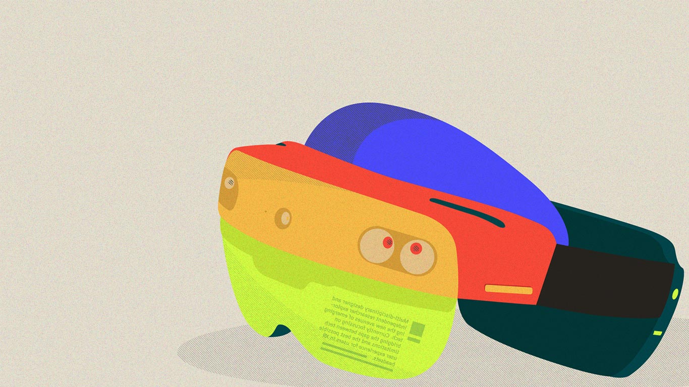
The current state of the typography in augmented reality
We have moved past the time when designers and typographers had full control over the medium in which people read. Now in practice, we design for certain use cases, beyond which we have limited/no control over how and where (device, platform, window size etc.) the text is going to be read. Responsive layouts have helped in gaining more control over extended use cases. However, the current use of text requires rendering once when it is loaded or when there is a change in parameters, such as layout.
Now let me introduce you to a new avenue (not new for game designers at all), dynamic text rendering. In a game or an augmented reality app, the camera/point of view (POV) is constantly moving. The glyphs in these cases are rendered continuously based on the movement and the size of the text is never the same from one frame to another. Such issues created the need for dynamic rendering of text with high-quality output.
It was conventionally solved by using pre-rendered glyphs stored as texture atlas for rendering text. Though it is fast in terms of rendering, it produces blurring and other text-related issues once the size of the glyph goes beyond what is saved in the atlas. Some of you might be wondering how the text size can increase while running the app? Imagine that you are wearing an AR headset and using a navigation app or playing a first-person shooter game. There is signage in front of you and as you move closer to it, the size of the text in it will increase to emulate real-life*. With every step you take towards the signage, the app has to generate (render) new frames of text continuously.
*The discussion here is based on the spatial application of the text, where text flows in free space as opposed to text sticking to the HUD (heads-up display). In HUDs, the text remains stationary in one place.
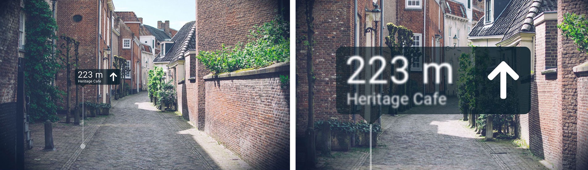
While designing the app, the designer would have set a standard optimum distance from where the signage is supposed to be viewed and s/he would have set the text size accordingly, let’s say 30pt, based on that size a text atlas is created. But if you are so curious that you end up going closer than one metre then the text will become blurred and distorted. Assuming that you are at a distance where the perceived text size is 70pt, at this stage the text is being generated using a 30pt text atlas which is similar to enlarging a 30pt bitmap image to 70pt (figure 1).
1. Designing for AR
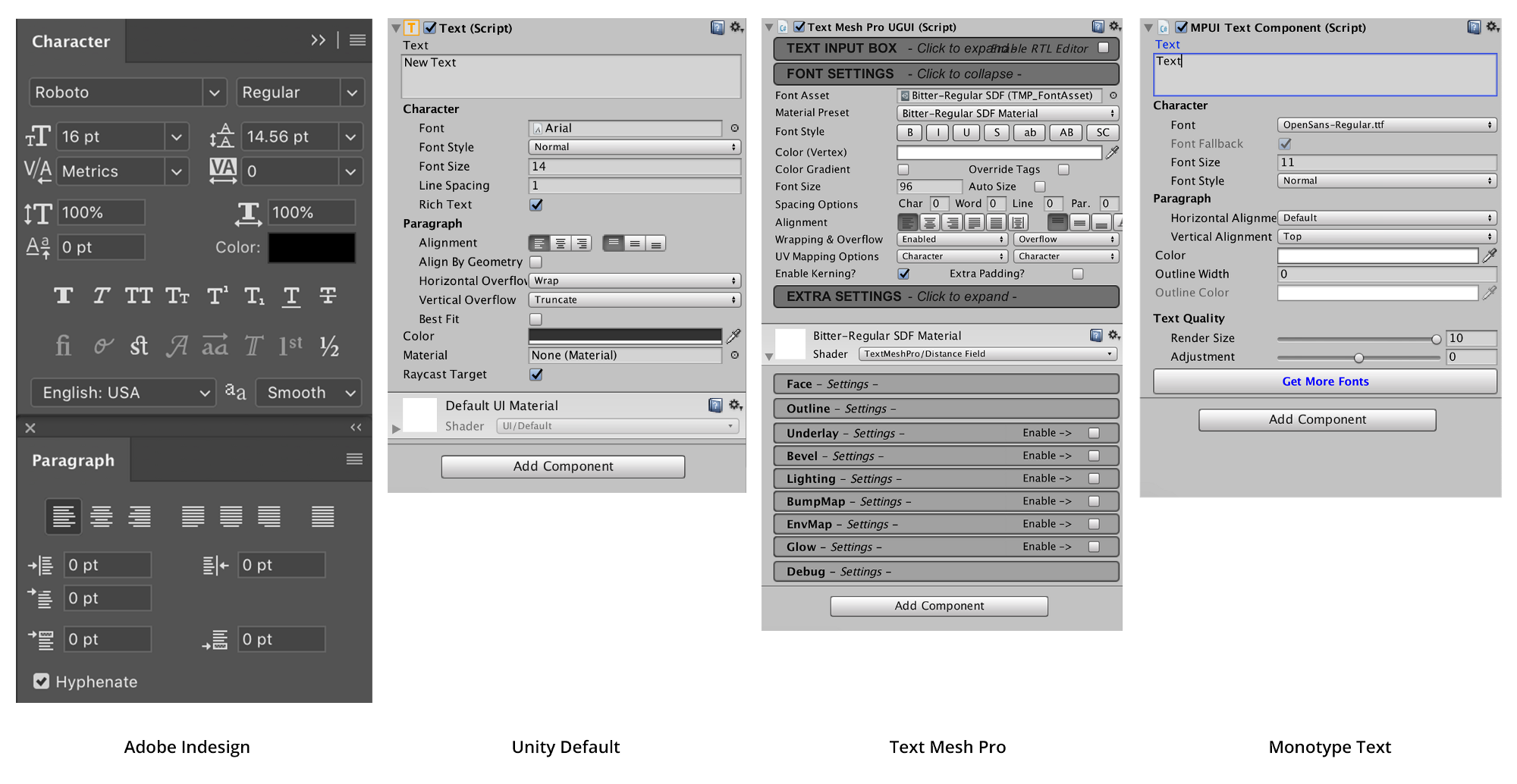
AR applications are being made using software platforms like Unity and Unreal engine that were designed to create games and other 3D applications. Since most of the games use the Latin script and have limited text usage, the need for features like ligatures, kerning and world script support has been low. The limited use is the reason these applications have less evolved features as compared to any other design application like Adobe Photoshop and InDesign (figure 2).
This article will primarily focus on Unity since it is emerging as the main platform of choice for AR content developers and hardware companies selling AR headsets. Currently, there are three ways to render text in Unity: default UI Text/Text Mesh, TextMesh pro plugin and Monotype Text plugin. All three of them use different ways to render text and have benefits over others based on the scenario.
2. Unity’s Default (Deprecated and Replaced by TextMeshPro)
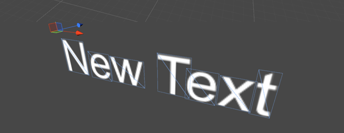
Unity offers multiple ways to use the text based on the type of usage. For 2D text, the “UI Text” component is recommended and “Text Mesh” for 3D text which is extensively used in games. The supported file formats include TrueType (.TTF) and OpenType(.OTF). For using fonts in applications/games the font files have to be imported as assets in the Unity project and once the font is imported it is rasterised and packed into two assets, “font material” and “font texture 1” Unlike other applications which use text outlines to render fonts, the glyphs in Unity are rendered using quads (figure 3). The font size controls the number of pixels used in each glyph to generate texture and rendering beyond that size leads to the pixelated appearance of text.
In case the application requires text information that changes in real-time (e.g. location names while driving) the rendering has to be done on the fly. For this Unity gives an option to use Dynamic Text in font import settings. The Dynamic Text uses the Freetype 2 font rendering engine to create font texture in real-time and reduces the file size of the application by using system fonts, thereby replacing the need for font embedding. Content developers use this quite often when they require support for Asian languages or large font sizes that generate massive file sizes to accommodate font textures. However, Dynamic Text allows the embedding of font data using the “Include font data” option. When the font data is not included, and the font is not available in users’ systems, then Unity replaces the font based on a hard-coded global list of fallback fonts that are generally installed on the platform it is being used on.
3. Text Mesh Pro
TextMesh Pro is a popular alternative available for Unity users that produces better results using a signed distance field (SDF) technique and advanced shaders 3 to render text. Conventional bitmap fonts (Unity’s default) render fine when used at 1:1 font texture to screen pixels. However, if they are rotated or scaled up during the runtime of the application, then the quality degrades, and pixels or blurred contours start to appear.
3.1 Signed Distance Field (SDF)
It is a rendering technique in which every pixel indicates the distance from the closest element (pixel) which is used to calculate and generate a smooth continuous field by nearest-neighbour interpolation. To understand, let’s assume that the black part of the shape in figure 4 (left) is inside and the white parts are outside. The visual representation of the distance field in a 16×16 grid will be like figure 4 (right). Wherein every value is the distance to the closest edge point which is marked through lines in the figure and these values can be used to reconstruct the same shape in different sizes.
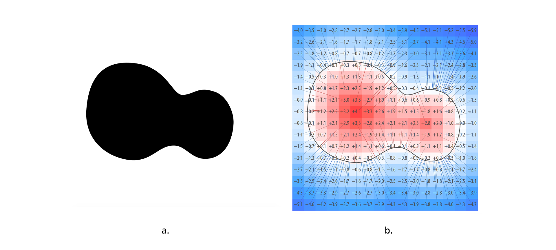
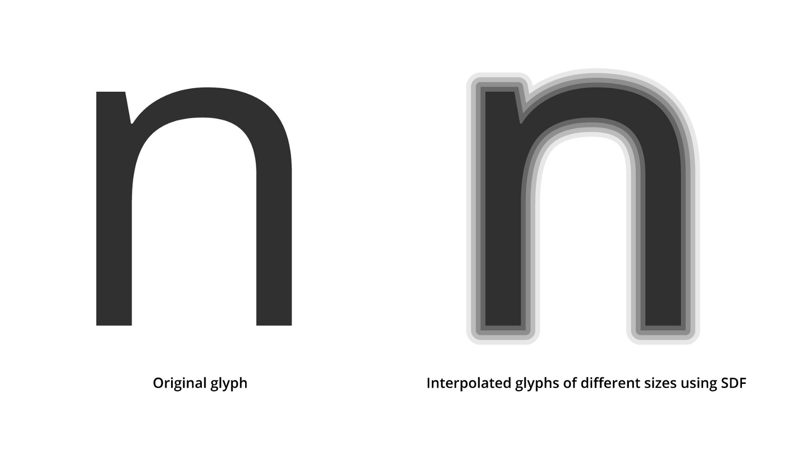
These values are used to reconstruct shape (glyph) at any resolution using simple interpolation (figure 5).
3.2 How does Text Mesh pro work?
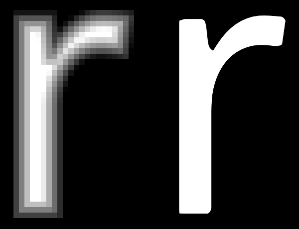
Text mesh pro converts OTF/TTF files into signed distance field font assets (font texture) using a font asset creator. The asset creator allows a wide array of options, including specific character sets and kerning pairs. Similar to Unity text, it does not support Indic scripts and ligatures. The SDF-based rendering is limited to the resolution of the generated texture, beyond which it retains crisp letter shapes but is unable to preserve the sharpness of corners and the rounding of edges occurs. For example: if a glyph is rendered at 64 pixels per em size and it is used to render size above that, the shape of the glyph becomes uneven (figure 6). The limitations are discussed in detail in section 6.1.
4. Monotype Text PlugIn (Deprecated)
In July (2018) Monotype released a plugin for unity named “Monotype Text Plugin” that uses adaptive distance fields which have some performance benefits over signed distance fields.
4.1 Adaptive Distance Field
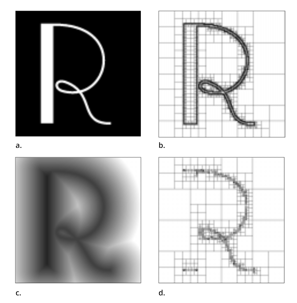
ADF is similar to SDF, it specifies the distance to a shape, where the distance is defined to distinguish between the inside or outside of the shape. However, the distance fields have drawbacks because of their size and resolution. In the case of fine details (serifs and gentle curves) dense sampling (saving of vector points), and a large quantity of data is required to accurately represent the details using a conventional distance field, even if the details occupy only a small fraction of the shape. ADFs use adaptive detail-oriented sampling wherein high sampling is done only in the part of shapes where the distance field contains fine details (see figure 7). Selective high sampling allows for efficient memory usage while rendering the text and better accuracy of curves.
4.2 How does Monotype Text work?
The plugin supports global languages with full support for complex shaping in languages like Arabic, Indic and Thai. The distance field generation is handled automatically by importing the font which is more efficient than importing the fonts and converting them to an SDF asset to be used in the project (how TextMesh Pro functions). Another useful functionality is the ability to change the thickness, the sharpness of the text on the fly depending on the headset, lighting and background.
Surprisingly, Monotype Text PlugIn has been removed from the Unity Asset store and is no longer available for download.
5. Other Techniques
This section talks about some alternative techniques which are being explored to improve the quality of the text. In the future, you might see one of these being used in seamless AR experiences across platforms.
5.1 Multi-channel Distance Fields (MDF)
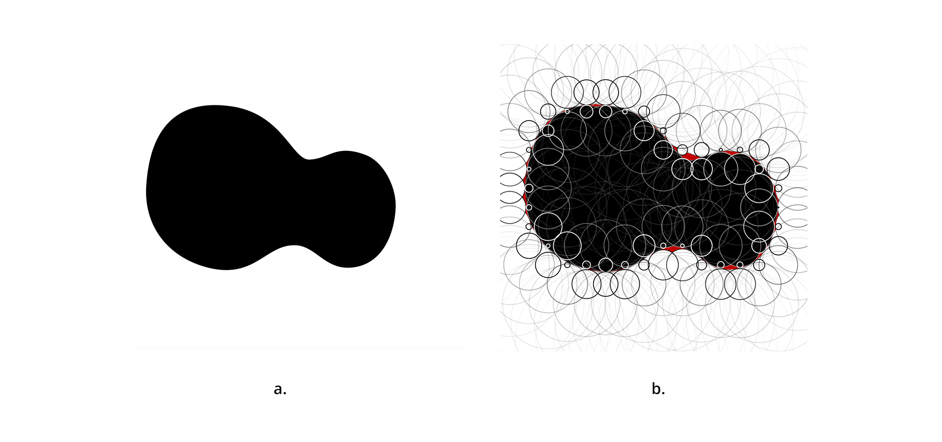
Multi-channel distance fields are an advanced version of SDF that addresses the shortcoming of SDF by using multiple distance fields. Considering the same shape shown in figure 4 drawn on a 16×16 grid, the SDF generated for it holds information about the shape that is used to recreate it in different sizes. However, the values are lossy, which results in rounded corners and other artefacts. This can be understood by the following example: if we plot a circle for each point of the grid using the signed distance as its radius then it would appear like it is shown in figure 8. The condition is that the circle should touch at least one point of the shape (black shape), but it should not intersect. This gives a clear boundary between outside and inside circles. This leads to a space that does not coincide with any circle, this area/part of the shape is where distortion(rounding) of shape occurs and details are lost.
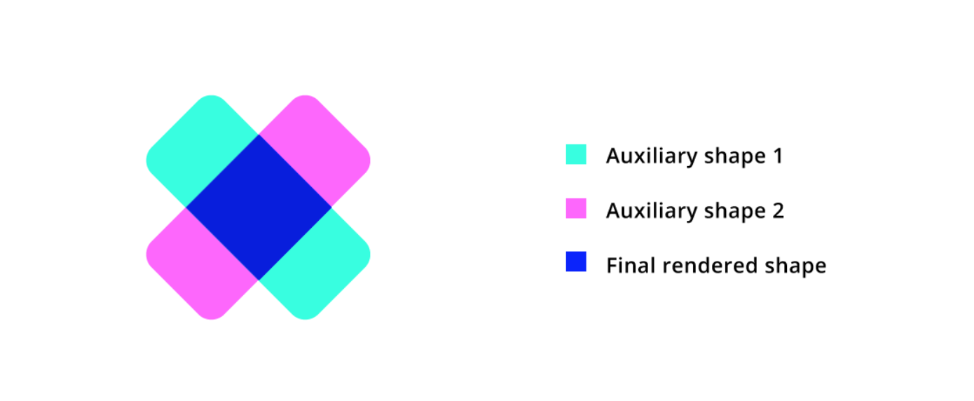
In multi-channel distance fields, more than one distance field is used to generate the final shape. First, the auxiliary shapes are constructed and then the overlapping area is filled with pixels to render the final shape (figure 9).
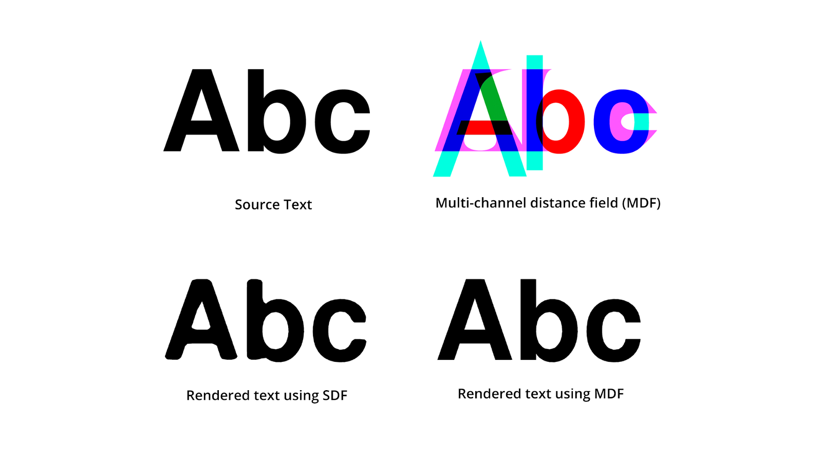
The distance fields are stored as monochrome images. However, image files are capable of storing at least three colour channels, in some cases, up to four. This makes it easier to encode two separate distance fields as one image where each channel holds one. Figure 10 shows the extent of improvement using MDF.
5.2 GPU Centred Font Rendering
The techniques discussed earlier utilise the original glyph description (Bezier curve info) and use CPU to produce an image of the glyphs as final rendered text. An alternative method is to directly render from vector data (outlines) of the glyph shapes using graphics processing unit (GPU) i.e the graphics card. This allows resolution-independent rendering because the exact positions of the outline’s control point are used to render the glyphs without any prior sampling. This has been an active area of research and experimentation and several attempts have been made to make it work. The GPU-based rendering produces high-quality results as compared to distance fields. However, they are hardware intensive and require a large amount of computing which uses more power, as well as higher rendering time, which makes it hard to implement in conventional hardware being used at the moment.
(To know more about alternative techniques refer to the links mentioned at the end of this article.)
6. Impact on type design
Rapid advancements are happening in the hardware and software parts of AR implementation, but it is clearly visible that text is a matter of least concern to engineers and developers at the moment, as the need for extra processing power for proper rendering of text has been an excuse for a long time. This pushes the AR designers to shy away from the text, using the least CPU-intensive ways to render text, thereby hampering the quality of the text.
As a type designer, we spend countless hours to get that right shape and in the end, if we see the whole thing rounded off or distorted, that is a huge blow to the heart.
AR is no fad that is going to fly away in no time, it is the next phase of wearables that are going to replace smartphones and computers. Based on current progress it seems that processing power availability of text will take time. But I feel that it should not hinder the progress of the application of AR by making it limited to graphic-oriented apps with the least amount of text. One way to do this is to design typefaces that can take the beating of technology and still render as intended by the type designer. My research is about testing these structural and perceptual aspects of glyphs to enhance the reading experience in the long reading text. Upcoming articles will shed more light on these aspects.
Alternative techniques for rendering
- Charles Loop and Jim Blinn, Resolution independent curve rendering using programmable graphics hardware: https://www.microsoft.com/en-us/research/wp-content/uploads/2005/01/p1000-loop.pdf
- Chris Green, Improved alpha-tested magnification for vector textures and special effects: https://steamcdn-a.akamaihd.net/apps/valve/2007/SIGGRAPH2007_AlphaTestedMagnification.pdf
- Behdad Esphabod, GLyphy, glyph rendering using OpenGL:
https://github.com/behdad/glyphy - LambdaCube Font Engine: https://lambdacube3d.wordpress.com/2014/11/12/playing-around-with-font-rendering/
References
- Dobbie, W., GPU text rendering with vector textures, 2016 https://wdobbie.com/post/gpu-text-rendering-with-vector-textures/
- Lengyel E., GPU-Centered Font Rendering Directly from Glyph Outlines, Journal of Computer Graphics Techniques Vol. 6, ?2, 2017, http://jcgt.org/published/0006/02/02/paper.pdf
- Unity User Manual (2018.3), https://docs.unity3d.com/Manual/class-GUIText.html
Footnotes
- Font material defines the optical properties such as colour and whether it is dull or shiny. Font texture is an overlay pattern over the surface of the text eg: grains.
- FreeType is a freely available software library to render fonts. It is written in C, designed to be small, efficient, highly customisable, and portable while capable of producing high-quality output (glyph images) of most vector and bitmap font formats.
- Shader is a computer program that is used for the production of appropriate levels of light, darkness and colour within an image.
Leave a Reply